Featured Stories
-
Advantages of Shear, Razor and Crush Web Slitting Techniques
When choosing a slitting method, many factors must be considered, including interaction with inspection systems. -
Revolutionizing Lithium-lon Battery Manufacturing Advances in Slot-Die and Electrode Coating Technology
As the global battery market surges toward an estimated $328 billion by 2028, innovations in manufacturing processes are becoming increasingly... -
Nordson Divisions Collaborate to Achieve Unprecedented Flat Profile Time
Nordson Measurement & Control Solutions (a division of Nordson Corporation) is a global leading provider of gauging systems for the film...
News | New Products
-
Morris Packaging to Add New KY Flex-pack Plant
Bloomington, IL-based Morris Packaging plans to build a new $60.9-million production plant in Marion County (KY), a project that will create 276 full-time jobs.
-
Press Belt Manufacturer IPCO to Focus on Engineering and Service Expertise
IPCO will use Ligna 2025 to highlight the service and support services it provides to press manufacturers and WBP producers alike.
-
INX promotes seven Executives to Vice President positions
INX International Ink Co. has announced the Board of Directors has approved the promotions of seven key people to Vice President positions.
-
Bimec and Flex CA Strengthen U.S. Market Presence with a new installation at Cello-Wrap Packaging Inc.
Bimec and Flex CA proudly announce a new milestone in their U.S. market expansion with the recent commissioning of a state-of-the-art slitter rewinder at Cello-Wrap Packaging Inc, located in Farmersville - TX.
-
New Era Converting promotes industry veteran Stephen Pickett to controls engineering manager
New Era Converting, an IPCO company, has announced that Stephen Pickett is taking on a new role as controls engineering manager.
-
Fedrigoni Announces New Slitting Center for Self-Adhesive Labels in Germany in Q4 2025
The Fedrigoni Group - a world reference in the manufacturing of self-adhesive labels, special papers for packaging and other creative applications, graphic supports for visual communication and RFID
-
Advancing Label Innovation Through Collaboration
Packaging is a physical representation of a brand’s identity, and label converters play an essential role in bringing the packaging experience to life.
Expert Advice
Static Beat | Static Dissipator Locations
- Published: September 18, 2014, By Kelly Robinson
 Static must be controlled sufficiently to suppress sparks. Static charges on plastic and paper webs cause sparks that can ignite flammable solvent vapors and shock operators who must handle the wound rolls. These sparks also deposit spots of charge that can cause cut sheets to stick.
Many static dissipators are commercially available. Passive dissipators, such as static brushes, grounded pin arrays, and tinsel, can reduce a high level of static charge to a low level. And active static bars can reduce the static level to essentially zero. Excellent technology for dissipating static charge is available. The challenge is to install dissipators in the right places so that sparks are suppressed.
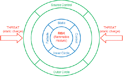
When identifying locations for static dissipators, think in terms of RISKS and COUNTER-MEASURES. Use the two-step process in Figure 1 to identify locations for your static dissipators. The first step is to identify areas at RISK from static sparks, such as C1D1 solvent areas and winding rolls. Any area of the process where sparks could cause injury, downtime, or product quality problems are RISKS. Our “Inner Circle” static dissipators are be installed to suppress sparks in RISK areas.

The second step is to identify charging sources using a static survey. Use an electrostatic fieldmeter to measure static on each accessible web span. The electric field on the web span exiting a particular roller or process that is a charging source is significantly higher than the electric field measured on the entering web span.
Common charging sources in Table 2 listed in red deposit enough static on a web to cause sparks. Sources that deposit ±5 μC/m2 of static charge cause the electric field to increase by ±6 KV/cm and sparks can occur. Our “Outer Circle” static dissipators are installed to dissipate static from each source of static charging.

RISK areas in Figure 3 are protected by “Inner Circle” static dissipators and static from each charging source is dissipated by “Outer Circle” dissipators. With static dissipators installed in these locations, our RISK areas are protected from static charge THREATS by a fault tolerant static control system. The failure of any single dissipator (Fault) is insufficient to expose the RISK to a THREAT.

Commercially available static dissipators have excellent performance. Our challenge is to install these static control devices to suppress sparks in RISK areas of our process. Static dissipators should be installed “best practice” locations to protect RISK areas with a fault tolerant static control system so that any single failure or fault is insufficient to expose a RISK to a static THREAT.
I invite you to ask questions about this column and to suggest future topics. My email address is: This email address is being protected from spambots. You need JavaScript enabled to view it..
Static control expert Dr. Kelly Robinson, president of Electrostatic Answers, has 27+ years of experience in problem-solving and consulting. Kelly writes PFFC's Static Beat column and the Kelly on Static blog. Contact him at 585-425-8158; This email address is being protected from spambots. You need JavaScript enabled to view it.; www.electrostaticanswers.com.


