


Web Tension Control Fundamentals
- Published: January 25, 2019
Abstract
Web tension control refers to the process of controlling tension while transporting a web. Accurate and stable tension control ensures the highest product quality and productivity. An optimized web tension control system will ensure that the correct tension is maintained for any type of material, at any section of the machine and regardless of speed or process conditions.
This paper is a review of the fundamentals of web tension control, covering the following topics; Machine sections (unwinds, rewinds and driven machine sections) and the critical tension control issues for each. Web tension sensors and components, dancer systems and accumulators. Load cell selection and dancer system design criteria. Methods of tension control, open and closed loop control. Modes of tension control i.e., speed and torque and their proper application. The effects of web compliance on tension control and control method considerations.
Machine Sections & Tension Zones
Most converting lines have more than one tension zone. The machine tension control zones can be considered as unwind, process or section isolation and rewind. Each zone will require a control system and isolation from the neighboring zone(s).
Unwinds
Roll to roll and roll to sheet converting lines start with the unwind section. Unwinds are center controlled, surface controlled or combination center/surface controlled. Unwinds can be configured as single or multi spindle or indexing multi spindle turret. Unwinds are controlled with a drive system or mechanical brake. The driven unwind is capable of achieving a higher level of tension control performance. A brake controlled unwind only operates in either of quadrants two (II) or four (IV), creating torque only in the opposite direction of shaft rotation (see figure 1). A driven unwind operates in all four quadrants of rotational speed and torque.
Figure 1: Quadrants of OPeration (n/M)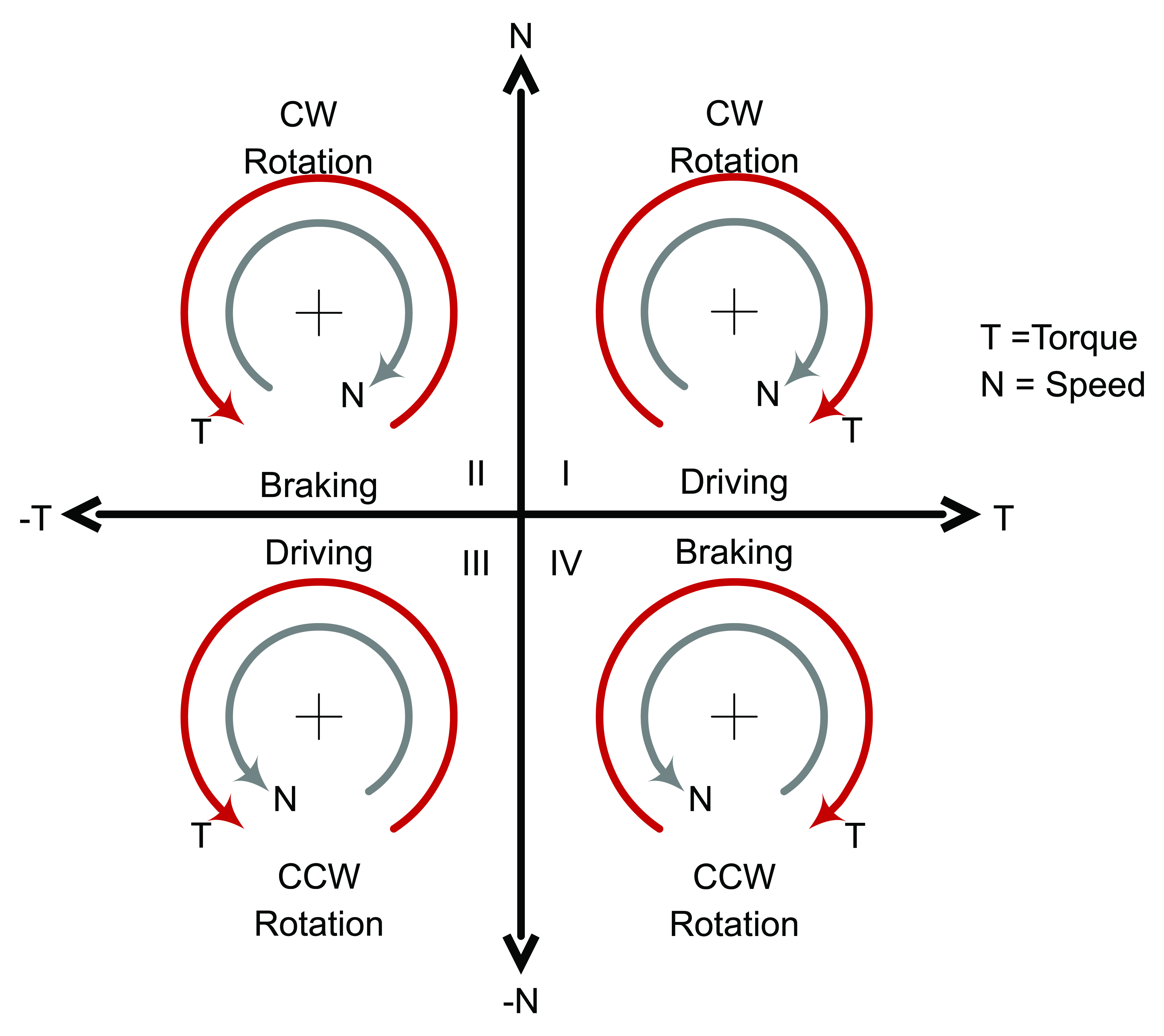
Unwinds require torque in the direction of shaft ration during acceleration and during roll created tension disturbances i.e., running out of round rolls or rolls with blocked material. Under single quadrant operation, the results of these issues are increased tension during acceleration and poor tension control during roll disturbances. An AC regenerative drive system applied to a driven unwind will provide control under those conditions and also have a wider torque range, better torque regulation and faster torque response, contributing to wider tension ranges, larger build ratios and greater tension control accuracy.
Additionally, AC drive systems have the ability to return regenerative energy back to the AC line, returning the tension energy back to the line that the brake produced as heat. When equipped with active front end technology, it will return the energy with near unity power factor. Beyond the obvious cost savings of pad replacements on mechanical braking systems, AC motors are virtually maintenance free by comparison. The combination of improved operation, reduced maintenance, power savings and energy conservation gives AC regen drives a clear advantage over mechanical brakes for controlling unwind zone tension.
Driven Machine Sections
A tension zone requires two components, a driven roll section and isolation, i.e. no web slip. The ideal tension isolating section is a driven steel pull roll with a pivoting rubber covered nip roll. S-Wrap driven roll sections can be employed but consideration must be given to the frictional qualities of the roll surface to insure isolation and eliminate slip. For processes that prohibit contact on both sides of the web, a Vacuum pull roll can be implemented. The vacuum pull roll is a hollow cylinder with a perforated surface that is internally connected to a vacuum source. The ideal vacuum roll will have adjustable side deckles to permit variable web widths. The better the zone tension isolation, the greater capability the driven sections can absorb tension transients. A driven machine section can be either the machine lead section or tension controller for the zone.
Rewinds
The rewind is the final section in a converting process line and in most cases requires the most critical tension control. Similar to unwinds, rewinds also fall into the categories of surface and center driven and combination. Where the pure surface drive on an unwind is normally belt driven, surface driven rewinds are normally of the two drum type. The center driven rewind is the most common. Center driven rewinds can be single spindle or multi-spindle turret. Taper tension can be an important option on rewinds and various functions can be implemented. A fixed taper tension can be used to reduce the power requirements of a winder drive system.
Tension Zone Control Challenges
Each individual machine section / tension zone can have its specific issues and challenges in optimizing its tension control. A driven machine section will consist of three components; a motor, power transmission components (gearing, couplings, etc.) and the load. Modern drive systems can provide a high degree of performance, but they depend on the quality of the power transmission mechanics. If the driven section has poor mechanical characteristics, that is, compliance or lost motion between load and motor, the tension control performance will be limited. All of the power transmission components should be evaluated for mechanical stiffness including coupling, shafts, and especially core chucks and shafts.
Poor wound roll quality (out of round rolls, blocked web, etc.) can be one of the greatest challenges for unwinds.
A properly designed dancer system can solve some of the effects inherent to quality issues. Self-optimizing control loops are now available and can be successfully implemented to reject cyclical disturbances but depend on a mechanically rigid system.
The tension control system on turret unwinds and rewinds should take into consideration the velocity changes to the web as the turret indexes. The addition or subtraction of web velocity should be included as a feed forward to the tension control system rather than letting the PID control determine and eliminate the error.
Consideration should be given to selecting the lead section or master, typically the closest driven section to the unwind or the section that requires the highest level of speed regulation accuracy. All of the following sections should follow the web velocity or web position setpoints rather than actual velocity or position values.
Tension Control
There are two control options for regulating tension in a zone; they are open loop or closed loop control. Both can be used to control tension in either a fixed diameter driven section or a center driven unwind/rewind. Tension control in the center winder is the most complex as it has to deal with the changes in circumference and roll mass. The following discussion on these two control options will focus on their functionality as center wind tension control
Open Loop Tension Control
Open loop tension control is typically selected for use when the cost of a tension sensor / control is a consideration. An open loop tension control system has no actual tension feedback from its control zone. Open loop tension control is based only on a tension setpoint without feedback or influence from actual conditions and does not have the ability to respond to tension disturbances in the zone. In a center wind application the control setpoint must be modified by the actual roll diameter to achieve the correct torque at the shaft. The diameter information can come from an external sensor or a diameter calculator. Tension accuracy will be directly dependent on the value of the systems diameter information.
Open loop tension control on center driven tension zones are implemented via torque control or torque limiting control in the drive. Inertia and friction compensation should be implemented in the control. At best open loop tension control accuracy will be in the range of +/- 10%. Open loop tension control in torque mode can be improved with the use of synchronous motors. The synchronous motors rotating magnetic field is constant, fixed by the permanent magnets in the motors rotor.
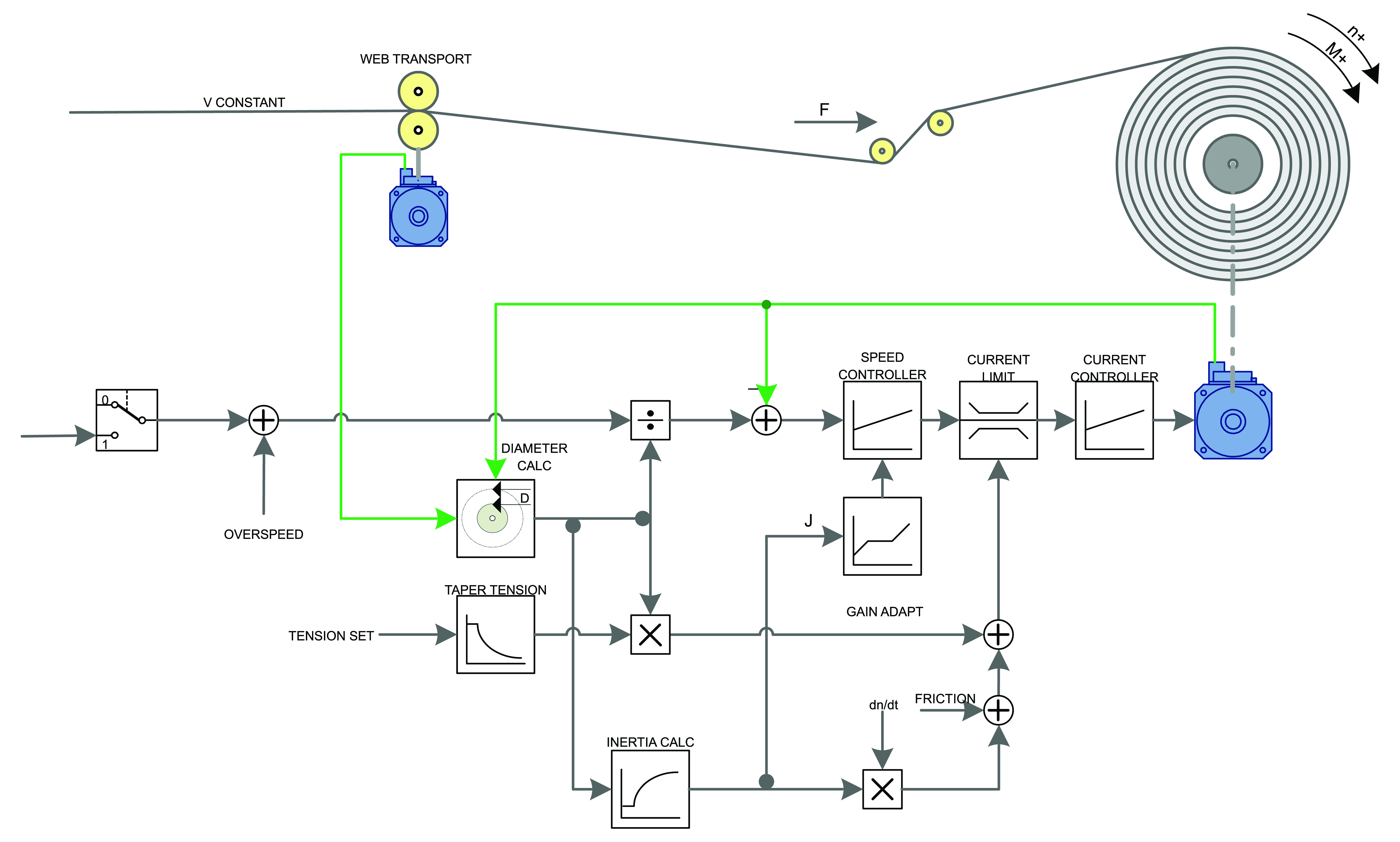
Open loop speed control or draw control can be used between sectional zones to establish web tension between sections where the web’s elasticity and zone length permit. The diagram in figure 2 describes the function.
Figure 2: Open Loop Torque Control – Center Winder
Closed Loop Tension Control
Closed loop tension control incorporated with either a (load cell) force measuring sensor or a dancer roll system to actively control the tension in a transported web. Load cell systems can regulate tension via speed or torque in the drive system. Dancer roll tension systems control tension by positioning the dancer roll through the drive systems velocity.
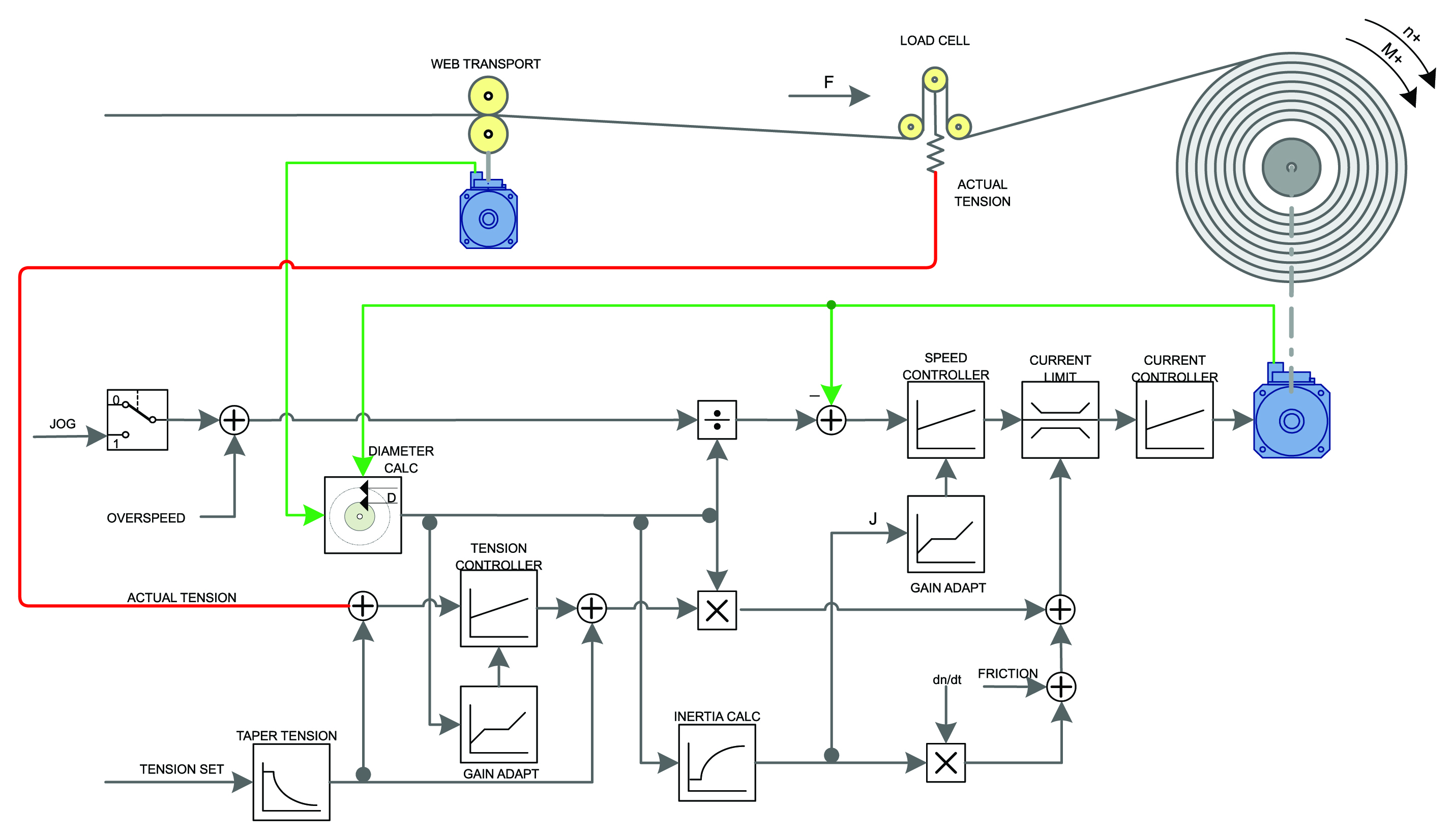
Closed Loop Torque Control is closed loop using load cell feedback, based on the tension setpoint reference, factored by the actual diameter and compensated by the actual tension error through a (PI) tension control loop as a rotational force through the current limits. Inertia and friction compensation are in most cases a required feature that should be implemented with this mode. The example in Figure 3 describes an example of load cell torque control.
Figure 3: Closed Loop Torque Control (with load cell sensing) – Center Winder
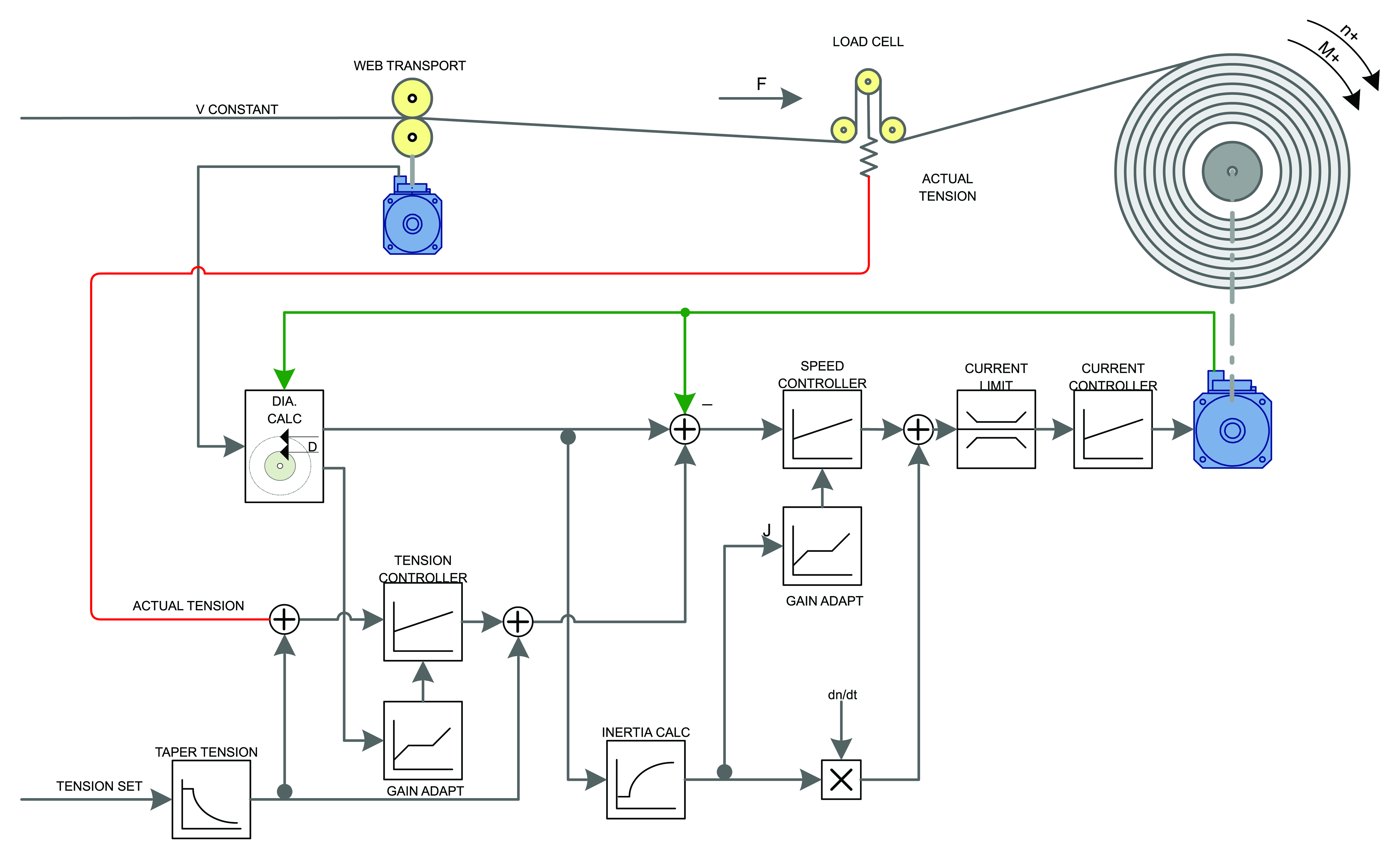
Speed setpoint Correction Tension Control is closed loop, with web speed reference and either dancer position or a tension feedback from a load cell. In this mode the feedback device can be either a dancer position or load cell, factored by the actual diameter and compensated by the transformed tension error through a PI (tension) control loop as a speed setpoint addition. Inertia and friction compensation are not as critical as the torque control mode however they should be an implemented as a control feature of this mode. The example in Figure 4 describes an example of load cell speed control. Closed loop speed control and torque control are the best options for accurate tension control performance.
Figure 4: Closed Loop Speed Setpoint Correction Control (with load cell sensing) – Center Winder
Web Tension Sensors and Dancer Roll Systems
There are two options for the sensing component of a closed loop tension control loop, Dancer roll systems and load cells or force measuring transducers. Both sensors have advantages and disadvantages that lead to selection in specific applications.
Dancer Roll Systems
A dancer roll system is not a tension sensor. A dancer roll system is a free moving idler, loaded with a force that is imparted to the web as tension as a result of the web positioning the dancer.
Dancer roll systems can be linear or pivoting. Linear dancers can have side to side alignment issues. Pivoting dancers are the most common, they can be mounted horizontal or vertical mounted either from the top or bottom. The most common usage of the pivoting dancer is horizontally mounted. Vertical mounting from the top tends to be self-centering creating a balancing or self-stabilizing pendulum effect on dancer motion. Vertical mounting from below tends to have stability issues as the dancer roll’s mass pivots through the center. The horizontally mounted units are the preferred type for optimum tension control. The typical range of motion for a horizontal pivoting dancer is +/- 30 degrees.
The dancer roll system requires a position sensor for the dancer position control. Traditionally the position sensor has been a potentiometer or similar analog sensing device. Because of the limited arm motion, direct coupled analog sensors (potentiometers) require gearing to extend the analog signal range. Potentiometers and other voltage driven analog devices are susceptible to electrical noise. PWM drives create the opportunity for induced noise on the low voltage signals of analog devices.
Optical encoders are the preferred position sensor of choice for dancer systems. Optical encoders offer noise free high resolution position data. For example, a sin/cos encoder of 22 bits of resolution provides over four million counts (4,194,304) of resolution per revolution, this equates to almost 699,050 counts of resolution over 60 degrees of dancer motion. This is more than significant resolution and eliminates the requirement for mechanical gearing of the position sensor. Using a sin/cos single turn absolute encoder will eliminate the need for homing.
The dancer roll system requires a rotational force (at the pivot) to be imparted to the web as tension. Various mechanisms have been used for applying a load force to the dancer, such as fixed or moving weights, springs, standard pneumatic cylinders, clutches on driven axes and etc. Pneumatically loading the dancer arm is the most common approach.
Eliminating friction in the dancer loading device is critical for accurate tension control. A change in web tension will produce a position change in the dancer arm. Friction will cause a delayed reaction to the tension upset and increase the tension error and delay the corrective response. The seals in standard pneumatic cylinders can have high breakaway forces. The breakaway forces increase with the size of the cylinder bore. Decreasing the bore size of a cylinder will reduce the breakaway force but it will complicate the mechanics of obtaining a sufficient force.
Rolling diaphragm pneumatic cylinders are commonly used for loading dancer arms. This type of cylinder provides practical low friction operation and is produced in a wide range of sizes that range from 4 sq. inches to 24 sq. inches of cylinder area. For the lowest friction requirements, the cylinder should be specified with linear rolling bearings in the shaft support instead of the standard sintered bronze bearing to decrease friction. The cylinders are supplied with an internal loading spring; the springs should be removed as air pressure provides a more linear force. A single loading cylinder on one side of the dancer arm is recommended. Mechanical stops should be implemented on the top and bottom of the dancer arm stroke to protect the cylinder.
An E/P or I/P (voltage to pressure or current to pressure pneumatic regulator) provides the best means for a remotely adjustable pressure control. The regulator selection must have sufficient forward and reverse flow in order to maintain constant pressure during cylinder volume changes. Any volume change in the cylinder without compensation from the pressure regulator will result in a pressure deviation, causing a tension error.
The tension range for a single roll pneumatically loaded dancer is dependent on the usable range of air pressure. For example with a maximum air pressure supply of 90PSI and a minimum usable air pressure of 5PSI, the tension range would be 90/5 = 18:1. The tension range can be increased by adding additional idler rolls to the dancer arm, therefore increasing the force on the arm by double with each additional roll.
The mass of the dancer arm should be designed to be as low as possible. Newton tells us in his first law of motion that “A body at rest tends to remain at rest and a body in motion tends to remain in motion.” Forces required to overcome a change to the resistive states in the dancer arm will be affected by the arms mass or inertia. The addition of a compliant web as the control coupling further complicates the issue. As the dancer roll system is a position controlled device, with web velocity and web material coupling the controlling factor, consideration should be given to implementing a design of minimum mass in the pivoting dancer roll as the highest priority. This is especially a critical for low tension webs. Some dancer systems incorporate counterweights to balance the arm. Counterweights should be avoided as they add mass to the dancer arm. Dancer system mass can be kept to a minimum by using aluminum components in the rotating arm structure and rolls. Ultralight rollers with dual bearing stub shafts are preferred, if a dead shaft idler must be used, steel shafts should be avoided.
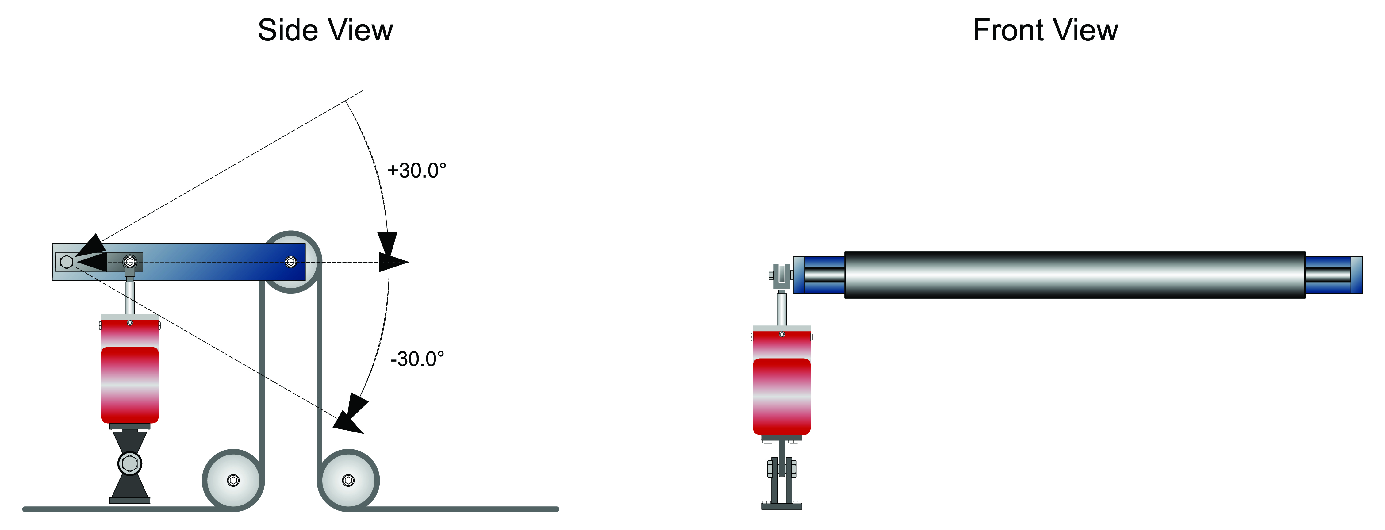
A properly designed dancer system will not only regulate tension well but will be able to absorb transients to the web without causing additional tension issues. Figure 5 describes a horizontally mounted pneumatically loaded dancer system using a rolling diaphragm cylinder.
Figure 5: Pneumatically loaded Dancer System
Accumulator Systems
Accumulators are used for web storage when one section of the continuous process must stop, for example to spice in a new roll or remove a piece of defective web. In the case of the unwind section stopping the accumulated web storage empties in order to continue the process. In the case of the rewind stopping the accumulator is filled. After the splicing is continued the accumulators return to their normal state from over or under speeding the proper section.
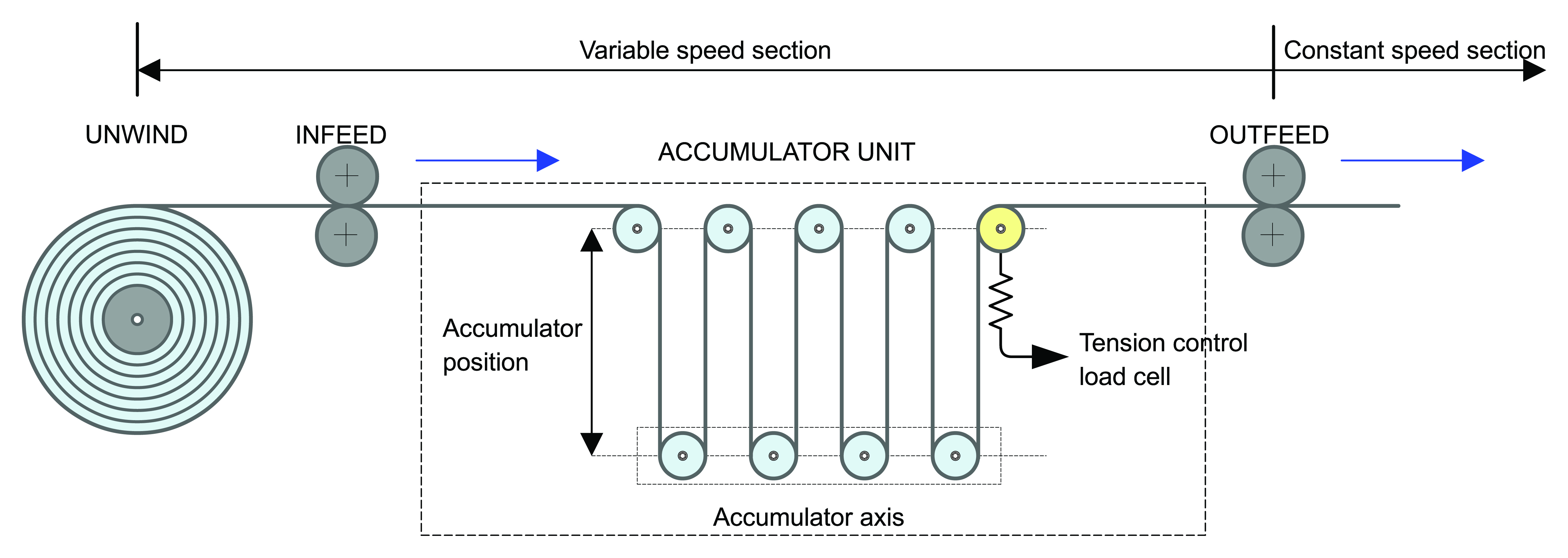
There are two basic types of web accumulators, one type is in general a loaded dancer with significant storage, the other type uses a driven position controlled carriage that is controlled by a tension sensor. Similar design criteria and recommendations that apply to dancer roll systems apply to the force loaded accumulator. In general the driven carriage style of accumulator operates with closed loop tension control and offers superior tension control results in web speed transitions. Figure 6 shows an example of a driven accumulator in an unwind section.
Figure 6: Driven Unwind Accumulator
Load Cells and Tension Transducers
Load cells and tension transducers are sensors specifically designed for the purpose of measuring the tension in a web, transforming the tension force into a proportional electrical signal. The electrical signal is amplified and used for display and or feedback in the tension loop control.
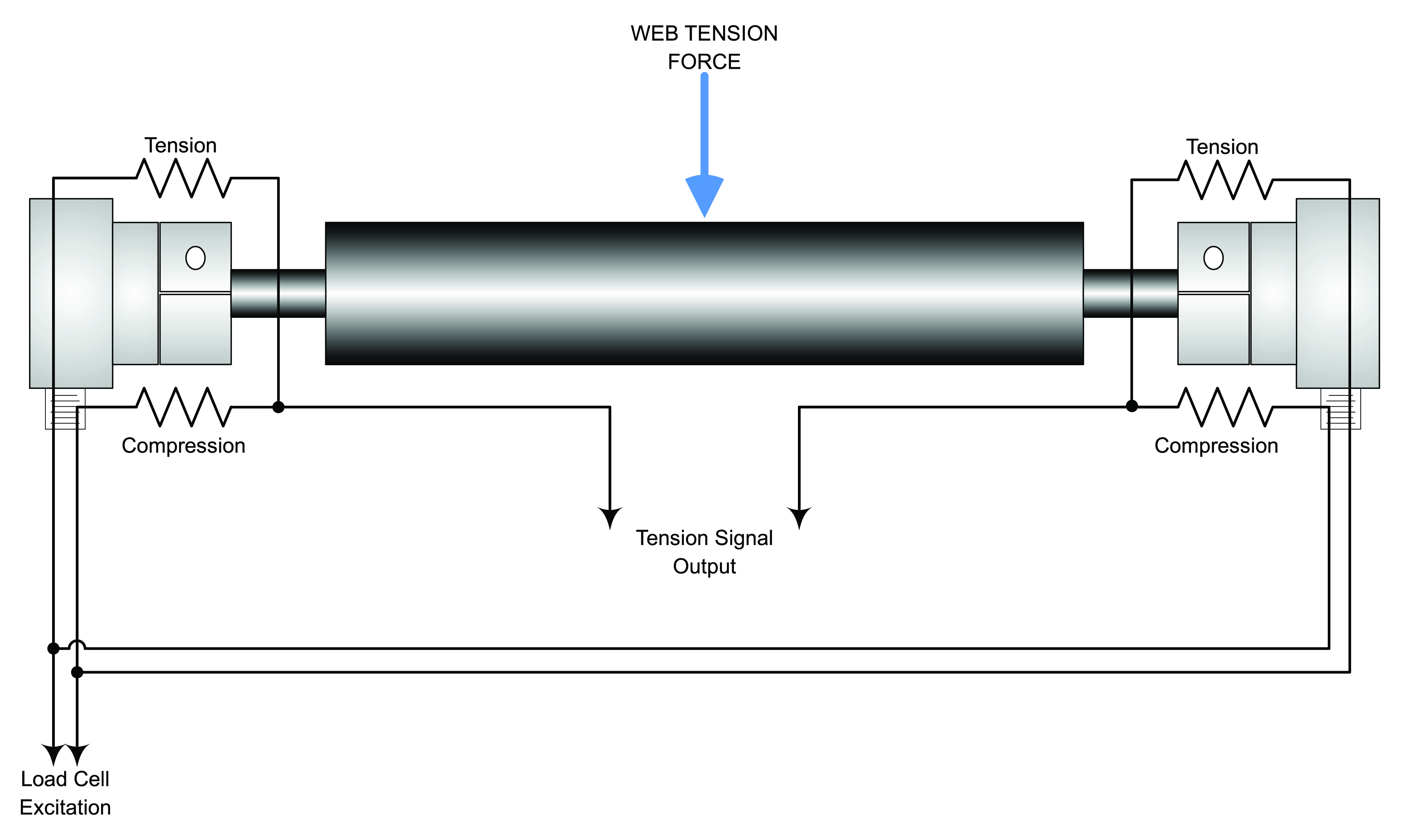
The majority of load cell designs use strain gauges as the sensing element. The strain gauge element can be foil or semiconductor. The load cells typically are mounted in pairs with each supporting an idler roll. The pairs combine and form a full Wheatstone bridge (some load cells do contain a full bridge in each sensor). Internally, the strain gauges are attached to a mechanical structure that deflects when a tension force is applied. The bridge reports the strain as an electrical signal that is proportional to amount of force applied (see figure 7).
Figure 7:
The output of signal of the load cell bridge is analog in the mv range, typically up to 250mv at rated output. In traditional systems the output signal was fed to an analog amplifier that provided a voltage signal to tension control system. Today most load cell manufacturers and third party companies supply load cell amplifiers with outputs to most of the common industrial networks. The benefits of network based amplifiers are numerous, they can be field mounted close to the load cells reducing the length of the mv level signal cables. The digital network signal to the tension controller offers better noise immunity to an analog voltage signal. The amplifier typically can be calibrated via software tools from the tension controller. The interface can be a direct signal to PLC control system.
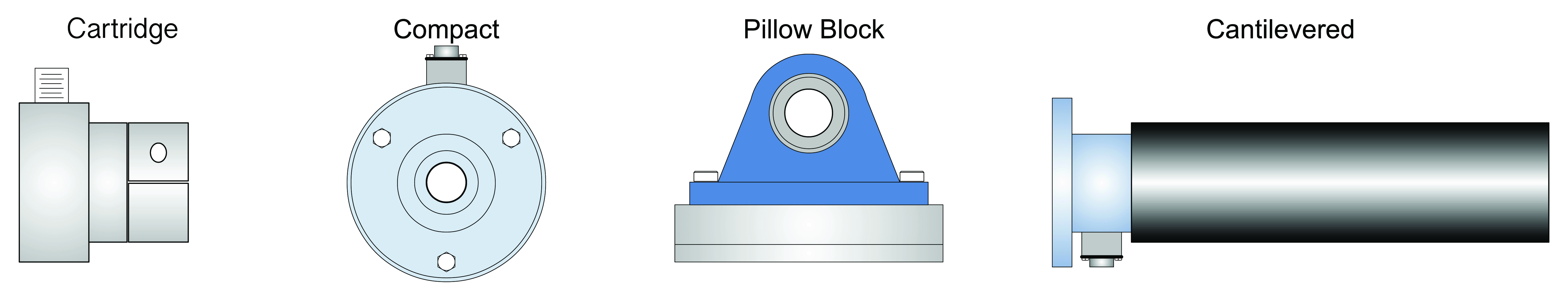
Load cells are available in cartridge, pancake pillow, block and cantilevered roll mounting types. The cartridge type utilizes a dead shaft idler roll while the compact type mounts with a live shaft roll with the bearings in the load cell housing. The cantilevered type includes a full Wheatstone bridge in the single load cell (see figures 8).
Figure 8: Load Cell Styles
Load cells are offered in a wide range of tension sensing sizes or “force ratings.” The force rating is in regard to the maximum tension force, typically called the “MWF”, maximum working force. Optimally the load cell should be selected as close as possible to the maximum tension requirements. Another consideration in load cell selection is the tension range of the load cell. The ranges vary from manufacturer. Historically, load cell tension ranges were no more than 15:1. Now load cells are available with tension ranges of 40:1 or even 50:1 and dual load cells (with two sensors) of ranges over 200:1.
Dancers verses Load cells
The question often arises, which tension device offers the best control accuracy. The answer to the question is complicated as each are meant for different application. The dancers function is to supply storage to absorb transients and the load cell for steady state tension regulation. Through proper design, both can perform equally well.
The storage capability of the dancer roll system offers a distinct advantage over load cells in the situation of web tension transients or fast web length changes, like those found on unwinds, zero speed splice and flying splice systems. The dancer roll system is more commonly used on unwinds and seldom used in zone tension control sections. Understanding and implementing good design criteria often limits the tension control performance in the dancer roll system. The dancer system does not provide a direct tension indication.
Load cells are inherently simpler and have fewer components in the system and are fairly low maintenance. They may however require periodical calibration. They have the advantage of inherent stability (lower gain) in torque control mode as the measurement and control are in the same medium (force). The measurement signals can be very accurate and cover a wide control range and offer excellent control capability under stable web conditions at any speed. Load cells do not have any web accumulation and therefore are difficult to use in splicing operations and in applications with severe tension transients.
Tension Control and Web Compliance
All web materials will displace or stretch with a force applied. The amount of this stretch will depend on the force applied and the webs modulus of elasticity or compliance. The selection of the winder tension control mode can be influenced by several factors, including machine specifications or design, the type of tension sensor used if any, but normally the major determining factor will be the compliance of the web material being transported.
The modes of torque control are commonly applied when the web material has a very low compliance or is “non-extensible,” e.g. polyester, heavy paper, steel, aluminum or other metals. With a non-compliant web, the higher system gain of a speed controlled system will make the system tend towards instability and much more complex to optimize tuning. The current or torque regulated modes of control tend to be more stable over a wider range of conditions. When implementing the torque modes, consider the closed loop mode with tension feedback if tension accuracy is critical.
The mode of tension regulation via speed control is preferred when the web is highly compliant or “extensible.” In this case the increased system gain from the drives speed controller help with the demands of the compliant web.
Conclusions
Understanding the fundamentals of web tension control can help in determining the issues that affect web tension control performance in each tension zone and lead to optimization. Careful tension system design and implementing current technologies will lead to improved performance and product quality.
References
[1] Control Systems for Web Fed Machinery; Herbert L. Weiss; 1983
[2] Drive system engineering for web fed machinery; William Gilbert; Aimcal Fall Conference 2014
About Siemens USA
Siemens Corporation is a U.S. subsidiary of Siemens AG, a global powerhouse focusing on the areas of electrification, automation and digitalization. One of the world's largest producers of energy-efficient, resource-saving technologies, Siemens is a leading supplier of systems for power generation and transmission as well as medical diagnosis. With approximately 379,000 employees in 190 countries, Siemens reported worldwide revenue of $94.0 billion in fiscal 2018. Siemens in the USA reported revenue of $23.7 billion, including $5.0 billion in exports, and employs approximately 50,000 people throughout all 50 states and Puerto Rico.