
An In-Depth Look at Extrusion - Part 2
- Published: October 12, 2018, By Christine Pietryla Wetzler
The purpose of the extruder
Single-screw extruders are generally divided into three sections, the feed, transition, and metering sections, as shown in Figure 1 below. The feed section brings plastic pellets (or powder) into the extruder barrel. The volume of the first flight times the screw speed time the bulk density times 60 is the output per hour. The transition section is where melting theoretically
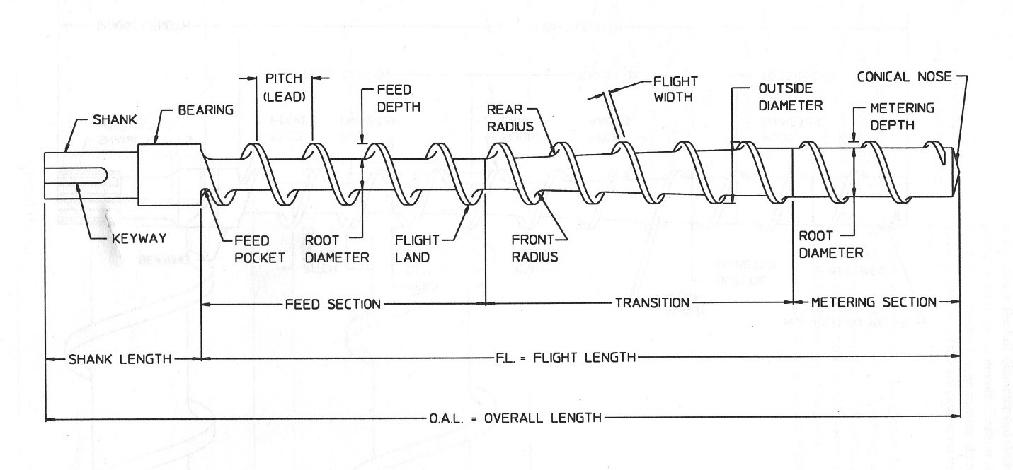
Figure 1. Extruder Screw Nomenclature[1]
As a reference for all future articles on this subject, Figure 1 is given showing commonly used extruder screw nomenclature. This well-established schematic dates back to the Golden Age of Plastics from Tadmor & Klein, Bob Gregory, Bruce Maddox
A hopper rests on the barrel above the first flight, and the feed pocket brings the plastic pellets into the extruder barrel, conveying them downstream to the transition section. The channel depth steadily decreases in the transition section, reducing channel volume, which in turn causes a restriction in the forward path of the pellets. This restriction simultaneously compacts the pellets closely together until there is no free volume between them, to what is called “the solid bed”. Tremendous pressure is creating during this compression section of the screw. The solid bed moves as one mass, creating intense friction between the solid bed and barrel wall. The coefficient of friction (COF) between the pellets/solid bed is largely responsible for the solids conveying angle in non-grooved, single stage, square-pitch screws.
The solids conveying angle can be thought of as the angle at which the solid bed transverses down the screw helix towards the discharge end of the extruder. Two coefficient of friction conditions

Figure 2. Two forms of solids conveying in a single screw extruder[2]
Bob Gregory, formerly of Egan Machinery, then a consultant to the industry, proved in the 1960’s that the COF is a maximum at the DSC (differential scanning calorimetry) melting point of the polymer plus 15°C. This is thus the ideal feed zone set point temperature.
With proper process conditions and screw design, the air between the pellets is forced
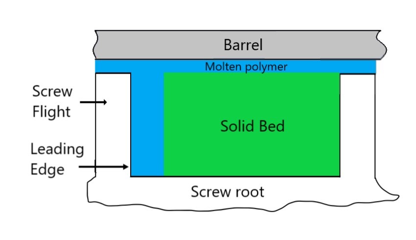
Figure 3. Melting Mechanism
The elimination of air, and thus oxygen, in the feed section prior to melt
If conditions are properly set, and the screw properly designed, melting begins at the end of the feed section. Figure 4 below shows this phenomenon, with the melt film starting at the fourth flight. These pictures were obtained from a “freeze-pull” experiment. It is not an ideal method to determine the location of melting, but it is what was available in the
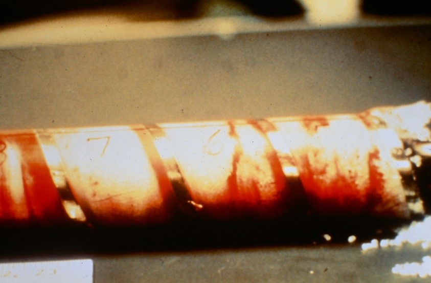
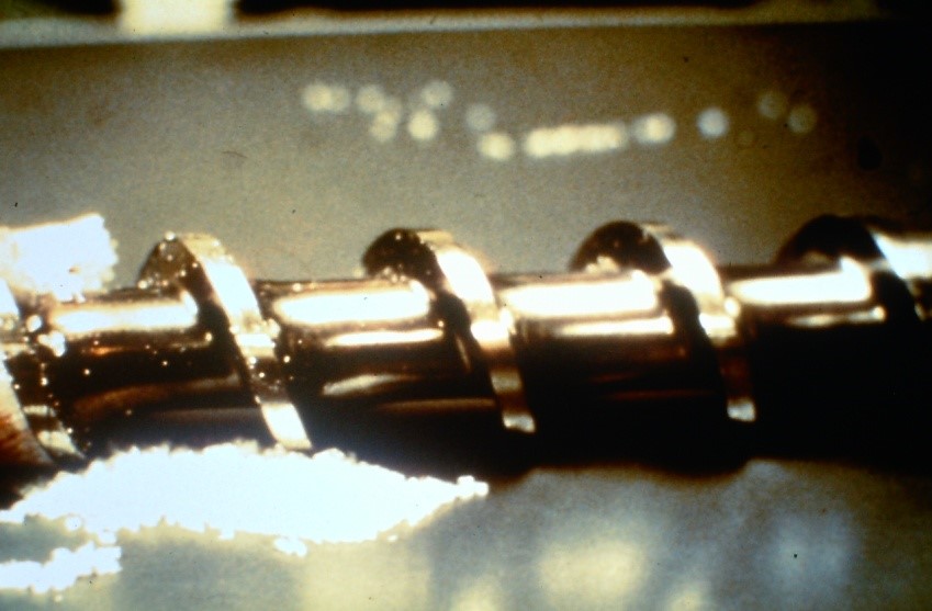
Figure 4. Melt film formation as determined from a “Freeze-Pull” experiment
In summary, the coefficient of friction between the pellets and barrel is critical. COF is maximized at the DSC melting point plus 15°C, which should be the feed zone temperature set point. Optimizing process conditions and screw design will maximize the solids conveying angle, and thus output, as well as melt quality and output stability.
Tom Bezigian holds a B.S. in Plastics Engineering from the University of Massachusetts–Lowell. He has been affiliated with the converting industry for more than 30 years and writes a column, Poly Ploys, for PFFC. It focuses on the field of polymers, laminations, and coatings with emphasis on R&D, quality assurance, manufacturing, marketing, operations, finance, and expert witness experience in the blown film, cast film, orienting, extrusion coating, and converting industries. He is the owner of PLC Technologies consultancy with over 30 years experience. Contact him at This email address is being protected from spambots. You need JavaScript enabled to view it..
[1]Plastics Components 2000, Spirex, p 6
[2] Bezigian, Extrusion Coating Manual, 4th Edition, TAPPI Press, 1999, p 38