


Tangent Shear Slitting | Reduce Edge Defects in Shrink Sleeve Film
- Published: January 05, 2018, By Sean Craig and Seamus Lafferty
When slitting shrink sleeve films, "razor sharp" may not be good enough.
Slitting is really just a controlled crack. When we study how things break or why they break we are in an area of science known as fracture mechanics. Fracture mechanics is a field of mechanics that focuses on what causes cracks to propagate in different materials or, more simply, the forces that separate things. However, while most analysis concentrates on how to prevent fractures, in slitting our emphasis is on how to control and focus the fracture. For this article our focus is on how best to control that fracture when slitting shrink sleeve films.
While it is important to understand the properties of all materials in order to achieve good slit quality, plastic film has some unique characteristics. Plastic films begin in a liquid state that is cooled to become the final product, whether that is polyethylene terephthalate (PET), oriented or bi-oriented polypropylene (OPP/BOPP), polylactic acid (PLA), polyethylene (PE), or some other form. Due to the “plastic flow” characteristic it exhibits, plastic film reacts to obstacles in its path depending on velocity, density, rigidity, temperature, crystalline structure, and shear characteristics. Needless to say, the act of slitting film involves placing a significant obstacle in its path.
Today, many films are slit with razor blades. They are inexpensive and they serve the market well for many general film slitting purposes. However, shrink sleeve film has a unique requirement in that the edges of a piece of film are brought together and bonded with a solvent to form the tube, or sleeve, that fits over the product and is shrunk in place. As such, this edge has more unique requirements than film that remains in a flat form. For shrink sleeves, the edges must come together perfectly both to align and create a visually transparent seam, and they must be bonded together with a solvent and not fail or distort during the shrinking process.
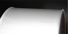
Finished roll edges that are “curled,” like those in the image in Figure 1, significantly jeopardize the bonding of the two edges. The result is rolls that are “blocked” due to solvent flowing through the scalloped edges or visibly poor seam quality due to solvent not flowing to, or being placed on, the very edges of the film. The culprit here is often the slitting process used—razor slitting. Let’s take a look at why “razor sharp” is just not good enough.

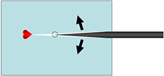
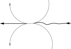
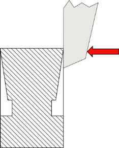
Razor slitting produces an inferior result primarily due to the fact that it induces lateral tensile stress forces across the web (cross-machine “Y” mode – Figure 2). When engaging the web, the razor creates a “controlled crack” ahead of the blade edge. The physical properties of the material and the shape of the blade edge determine how and where this crack will form.
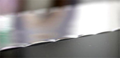
The farther away from the tip of the razor the crack forms, the less stable the process. Edge flaws (Figure 3) may develop, and uncontrolled tearing or splitting may occur.
Additionally, the properties of the material yield different crack characteristics.
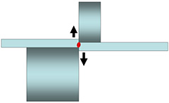
Low elongation or thick materials “crack” farther ahead of the blade edge while high elongation or thin materials “crack” closer to the blade edge (Figure 4).
Furthermore, the ratio of web tension to the material’s yield stress must be considered. Since the blade is dragging against the web, this frictional resistance must be factored in with the tension force. A general guideline is that the web tension in the slitting zone should not exceed 10% of the material’s elastic limit. (Ref: Wm. Hawkins Plastic, Film, & Foil Web Handling Guide). Otherwise, as the film passes the blade shoulders, the additional drag from the blade, combined with web tension, could exceed the film's elastic limit. Fragmented, stretched, thickened, and deformed edges are the result.
Another option exists that should be carefully considered for the benefits it provides to slitting shrink sleeve films: Tangent Shear Slitting.
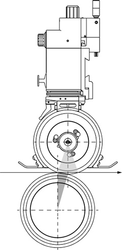
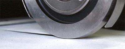
In a tangent shear slitting system, a round upper blade and lower anvil contact each other at a specific, synchronized point—called the nip—in order to concentrate the forces on a given material to create a controlled fracture. This controlled fracture that separates one piece from another piece in such a way that a nice, clean edge remains. Different from razor slitting, tangent shear slitting leverages shear stresses in the vertical (“Z” mode) to avoid lateral cross-web conflict (Figure 5). With shear slitting, the forces are perpendicular to the crack, the crack is sheared out-of-plane and crack propagation is concentrated in a precise and focused location.
System Set Up
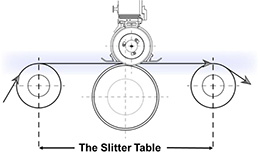
We are going to talk about the specific factors that need to be controlled at the crack in tangent shear slitting, but first let’s address the overall set-up. Tangent shear slitting begins with a properly configured shear slitter table, comprised of an infeed and outfeed idler on either side of the slitter anvils (Figure 6). Regardless of the material, this table should have the idlers spaced as close to the anvils as possible in order to suppress web flutter. Also, the optimal ratio for the lower anvil to the upper blade is 1.5:1.0; that is, the lower blade should have a diameter that is 1.5 times the diameter of the upper blade. A typical size is a 90mm upper blade with a 150mm lower anvil.
At the slitter table the web must not be disturbed by any outside force as it passes over the slitter table. Maintaining uniform tension, speed, flatness, and guiding across the entire length of the slitter table are imperative to producing a quality slitting result.
Another important element is to manage the tension at the nip point. The goal is consistent tension across the web with the tension set not to exceed 10% of the product yield strength. This can be managed through the unwind tension or by isolating the tension zone at the slitter table. The rewind tension should be set to achieve the desired roll profile following the slitters.
From the general setup of the tangent shear slitting system, we move to the specific factors that must be controlled in order to successfully slit any material, including shrink sleeve film. Shear slitting relies on the principle of slitting at a nip point, the point where the upper blade contacts the lower anvil. Similar to a pair of scissors, this point must be closed in order to slit any material. Keeping this nip closed requires the converter to manage the following six critical factors:
- Slitter geometry
- Overlap
- Overspeed
- Blade profile
- Cant angle
- Side force
Slitter geometry ensures that the correct blade profile combined with the correct cant angle and overlap, coupled with proportionate side force, places the nip at the optimal position to provide the best slit quality. Correct slitter geometry is fundamental to achieving the desired slit quality with shrink sleeves. While the knifeholder itself should manage cant angle, overlap, and side force, its relative position to the web and lower anvil must be set up correctly.
For tangent shear systems, this typically means offsetting the upper blade relative to the centerline of the lower anvil between 3mm and 10mm, depending on the size of the upper blade and lower anvil (Figure 7).
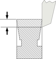
Overlap refers to the distance the upper blade extends below the top of the lower anvil (Figure 8). Too little overlap and the blade can jump on top of the anvil; adequate overlap helps ensure the nip remains closed. Lighter materials slit well with 0.015 in. to 0.030 in. overlap but denser, stronger materials may require additional overlap. Overlap also has a significant impact on overspeed, which is defined below. Additionally, overlap can affect whether the web is supported at the nip point. Too much overlap moves the nip point beyond the supporting surface of the anvil, which can adversely affect slit quality because the material is now free to move away from the forces trying to slit it. Because we are also trying to minimize the movement of the shrink sleeve material through the nip, 0.010 in. – 0.015 in. blade overlap is all that needs to be used.
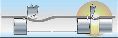
Overspeed means that the lower anvil and upper blade are rotating at a velocity that is faster than the approaching web that is to be slit, a condition that prevents the oncoming material from bunching up or slowing at the nip relative to the rest of the web that is outside the slit zone (Figure 9). With shrink sleeve films, it is important to be able to fine tune the overspeed for optimal slit quality.
Blade profile relates to the shape of the blade at the cutting point. For slitting shrink sleeve films, this factor is very important. The profile of the blade influences how the material passes through the nip point and around the upper blade. Incorrect blade profile for a given material may result in distortion of the material as it passes around the blade. Too narrow of a blade may result in reduced blade life and diminished slit quality.
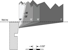
In Figure 10, you see typical blade profiles for tangent shear slitting. They range from nearly square to very acute angles and because the blade projects through the web while slitting, it has a significant impact on the slit web edge. As the material passes around the blade, the stress on the material at the nip point changes from a vertical shear stress with a square blade to lateral tensile stress with an acute blade.
Since shrink sleeve film is sometimes slit with razors, a natural conclusion is to use a very narrow blade for tangent shear slitting. In fact, the opposite is true. To better maintain the vertical shear stress we need for film, using a lower angle blade with a high finish tolerance on both the blade and the lower anvil actually produces better results for shrink film.
How the material passes the blade after it has been sheared or sliced is the other element of blade profile that is important to your slitting process. Remember, the web is literally in a head-on collision with the nip point and once the blade separates the web, it has to continue on past the blade. Blade profile directly influences this: a wider, square blade allows the film to pass under the blade where as an acute angle blade will force the material to pass around the blade, similar to a razor. We want the material to gently pass under the blade as shown in Figure 11.
Yet another variable that comes into play with film is the relative space between the anvils. For some materials, keeping the gap between the anvils on the unsupported edge very small provides additional support to the material. But tests have shown that actually allowing a greater gap for film prevents lateral crowding of the slit edge and therefore less damage to the unsupported edge.
Testing demonstrates that using a more acute blade with only a 1mm gap produces more edge “curl” than when using a less acute or more “square” blade with a 3mm gap between the anvils. This is because the low angle blade allows the material to deflect under the blade, maintaining vertical stresses; the additional gap allows the material to deflect without crowding (Figure 12).
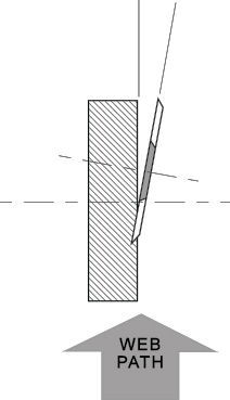
Cant angle is the angle at which the upper blade is positioned relative to the lower anvil (Figure 13). Zero cant angle means that the upper blade is positioned parallel to the lower anvil. In that position, most materials would simply fold between the two blades, similar to the manner scissors behave when they are too loose. And when you have a pair of loose scissors, how do you correct the problem? You force the blades against each other, a process known as “canting” the blade. In tangent shear slitting, cant angle is critical to keeping the nip closed. No slitting will occur in an open nip.
Side force, like cant angle, is critical to keeping the nip closed (Figure 14). Working in concert with cant angle and blade profile, side force is the resistance to those forces in the material trying to open the nip. More than anything, ensuring the slitters are set up properly and that the other factors for shear slitting are under control will minimize the amount of side force required. Most converting materials can be slit with as little as one to three pounds of side force, so avoid excessive side force when slitting shrink sleeve film. The function of side force is to simply keep the nip closed. Higher side force is usually only needed for heavier materials that tend to force the nip open.
We see that for slitting shrink sleeve films, “razor sharp” may not be good enough. If the converter is plagued by slit edge quality issues, then a proper implementation of tangent shear slitting may help reduce slit edge defects that wreak havoc on the shrink sleeve process. In summary, for optimal results in slitting shrink sleeve films, ensure the following items are in place in your process:
- Use a tangent shear slitting system
• Permits slitter nip synchronization
• Eliminates poor slit quality caused by lateral stresses induced by razor slitting
- Run with larger lower slitters
• >1.5:1.0 lower anvil diameter ratio
- Manage the tension at the nip point
• Do not exceed 10% of the material yield strength
• Isolate the tension at the slitter table when possible if material tension varies
• Permits varying tension to match the film's thickness and yield characteristics
- Run microfinished, single bevel upper slitters
• RMS 2-4 finish (mirror finish) – Blades and anvils
- Ensure adequate slitter gap
• Tangent system, unsupported side
- Ensure slitter has adequate overspeed
• Accommodates blade re-grind diameter
ABOUT THE AUTHORS
 Sean Craig is the general manager for Maxcess-Tidland. For nearly 30 years, Sean has been involved in the design and application of slitting and winding components for the primary and converting web handling markets. These products include reel spools, differential air shafts, pneumatic and electronic knifeholders, and large and small scale manual and automatic slitting systems. As GM for Maxcess-Tidland, he oversees operations at their Camas, WA, and Keene, NH, manufacturing sites as well as a repair center in Neenah, WI. Sean is also a regular speaker for AIMCAL and other industry associations. He resides in Vancouver, WA, with his wife, Sheila. In his spare time he enjoys cooking, cycling and hiking in the great Pacific Northwest. Contact him at This email address is being protected from spambots. You need JavaScript enabled to view it.
 Séamus Lafferty is president of Accraply Inc. Irish by birth, Séamus has lived in the U.S. for 17 years. A brief sojourn in the newspaper printing press business in New Jersey quickly led him to the southern Illinois-based Stanford company, which manufactured converting equipment for the flexible packaging marketplace. After identifying the growing shrink sleeve label market as a new direction for Stanford, Séamus helped grow the company and developed a personal reputation for his technical and market knowledge in the shrink sleeve area. Following Accraply’s purchase of Stanford in late 2007, Séamus relocated to Minneapolis and assumed the position of director of business development for the Stanford brand. That was followed by his appointment as VP of sales & marketing in 2009 and his promotion to president in 2014. Séamus recently co-edited Shrink Sleeve Technology along with Michael Fairley, published by Tarsus Exhibitions and Publishing Co., London. Contact him at This email address is being protected from spambots. You need JavaScript enabled to view it.