Screw Design for Film Extrusion
- Published: January 12, 2016, By Tom Bezigian
The screw is the heart of the extrusion operation. It is hidden within a solid barrel, the origin and condition of the screw are typically unknown. A lot has been said about films and processing, but what about designing and building extruder screws?
For extrusion processors, including those who produce blown and cast film, and extrusion coated and laminated products, the important things that an extruder screw does is deliver the desired output at the desired melt temperature and pressure, with a minimal amount of variation of each of these parameters. When this happens, gauge uniformity is optimized (at least in the machine direction). These are discussed in greater depth below.
Screw output: The screw must deliver optimally developed polymer melt, at rates that meet the throughput target of the processor. This is particularly important in view of the high volumes encountered in film production.
Melt quality: The mechanical, optical, and appearance properties are highly sensitive to the temperature and pressure of the melt, the efficiency with which colorant has been distributed, and the presence or absence of gels, degraded polymer, or other defects. These factors are directly affected by screw design.
Melt temperature: Besides affecting film properties, melt temperature is a critical factor in productivity, since the need for cooling places limitations on film line throughput. Because it determines the balance between shear heating and barrel heating, the screw design directly influences the temperature of the melt being delivered to the die.
Gauge uniformity: Consistent, uniform melt thermal properties are essential for gauge uniformity. A properly designed screw, often in combination with a gear pump, enables the die to maintain a uniform thickness profile. I spoke with Walter Smith, senior process engineer and Bryan Ramsey, design engineer, both at Nordson Xaloy. According to Bryan, "Successful screw design takes into account both the polymer and the processing system to be used. Some examples of design considerations are the bulk density of the feed stock, frictional properties of the resin, frictional properties of barrel and screw surfaces, specific heat of the resin, melt temperature, initial viscosity, and viscosity changes of the intended resin, along with such processing factors as the barrel heater layout and the head pressure generated at the die.
"In designing a Xaloy screw, Nordson engineers draw on a database of screw designs that goes back many years, and Nordson’s library of rheological data on resins, which includes thousands of entries. At the company’s rheology laboratories, customers can have materials characterized at no charge by sending in tiny samples."
On the processing side, Walter says, "Because melt quality is an especially critical factor in film production, screw designs often incorporate special elements or segments not found in a standard or general-purpose screw. These include mixing segments, both dispersive and distributive types, which provide improved color dispersion and more homogenized melt; and barrier segments, which solve problems of inefficient melting or over-shearing of already melted resin (particularly at high screw speeds).

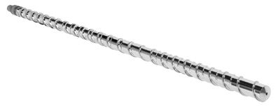
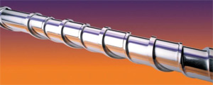
Barrier screws are screws with two flow channels, one for the molten material, and one for the yet-to-be-melted solid pellets, a portion of which is shown below. The designer calculates where melting will begin and places the beginning of the barrier flight at that location. The barrier flight volume is initially small, but it is continually increased by increasing its depth and width downstream.
Walter Smith continues, saying, "The deep melt channel provides lower shear than in a standard single-stage screw, and reduces the possibility of overheating the melted polymer. The solids channel becomes narrower and/or shallower, forcing the melted pellets against the barrel for efficient frictional melting. The solids bed continues to get smaller and finally disappears into the back side of the primary flight." These different flights can be seen in the image below.
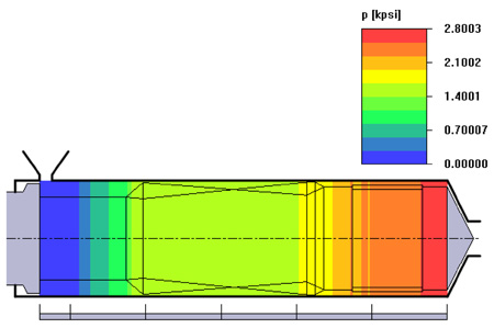
 Most modern, high-output, extruder screw designs incorporate a "mixing" section at the end of the extruder screw, downstream of the barrier section in the case of a barrier screw. The mixing section does more shearing and energy input than mixing, but this name was given decades ago, and it persists today. Calculating temperature rise is easily done by computer, as the energy input due to shear is a product of shear rate and shear stress. All the designer needs is the viscosity curve for the polymer, and an intelligent estimate of temperature rise in the mixing section can be estimated. The ultimate goal of course is to achieve the desired output at the desired melt temperature with a minimum amount of variability. The figure below shows a typical graph generated via computer simulation using Compuplast Virtual Extrusion Laboratory software.
 Gels are particularly problematic in film production, as they cause quality defects as well as cause breakage in films, particularly stretch films. It is important, however, to accurately determine the root cause of gel formation. Unlike gels from crosslinking or degradation, for example, unmelted material has the same color as the surrounding material and becomes increasingly worse with higher extrusion rates. For high-output lines, Nordson recommends either a barrier screw or a mixing element—or both, as in the Fusion screw.
Making an extruder screw is a long process. Once the design has been finalized, a rod of the appropriate length, diameter and composition are ordered for machining, as shown in the figure ![]() to the right. After the screw is cut, hard-facing is typically welded onto the screw flights. This is a delicate step can take a week to complete so that warpage of the screw is minimized. The screw is then kept in a large bed of sand so cooling takes place slowly, again, to minimize warpage. The screw is buffed, plated if necessary, then finally straightened on a large metal brake to ensure concentricity.
to the right. After the screw is cut, hard-facing is typically welded onto the screw flights. This is a delicate step can take a week to complete so that warpage of the screw is minimized. The screw is then kept in a large bed of sand so cooling takes place slowly, again, to minimize warpage. The screw is buffed, plated if necessary, then finally straightened on a large metal brake to ensure concentricity.
This is the short version. I hope to visit a manufacturer in the coming months to show this process in more detail.
I would like to thank Walter Smith and Bryan Ramsey for their contribution to this article, and Nordson Xaloy for the images presented above.


